Thursday, April 23, 2020

transformers vs iron dude

This post will be about the remaining two rack units, and a quick look at what's inside them. As I mentioned before, this vacuum chamber appeared to be used for the purpose of outgassing some kind of filaments (for mass spectrometers, maybe?). Once again, here's what inside the chamber looks like:

The image isn't blurry... You're just drunk!

You can see 3 banks of filament holders here, with each bank running to one of three cathode heating current power supply sections:

No, I didn't take a crappy pic.. You're just drunk.. Still.

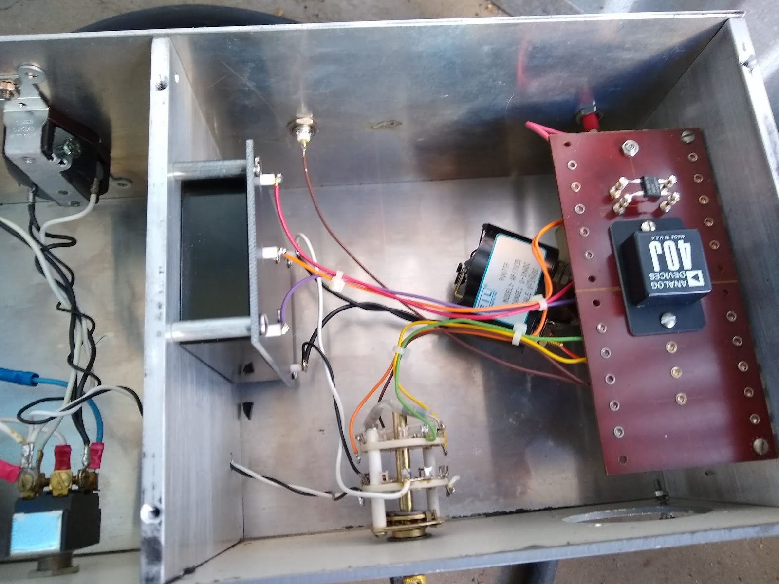
A look inside will reveal what's going on:


Pretty simple. Without having actually delved into it, line voltage comes in and is routed to the switches on the front panel, which then runs through the beefy wire wound pots (which all look to be in good condition. Nice!), setting the current through the primary side of the transformers. The secondary side goes through the panel meters and then to the filament banks. This is entirely AC. The interesting bit is the pink wire that's seen coming in through the rear of the enclosure to the right. Where does that go?


You can see the pink wire on the upper left side. The upper grey box with the twisted wires coming out of it is the power supply we just looked at. The lower box that it's plugging in to is what appears to be for setting the filament emission current, and so the pink wire carried that return current. This must have been a timed process, hence the timer. This was purpose built, and maybe one off equipment.


Center top of the last image shows a brown wire soldered to what looks like some kind of coax connector. This is connected to a plate mounted to the top of the chamber lid, partially visible in the first image of the post. That completes the emission current circuit.

I will need a filament power supply for my experiments, but I'll want it to be regulated DC. I'll probably reuse some of the above components for that purpose.

let ions be bygones

As seen in my previous post, the rack mounted electronics were some of the things that didn't fare so well during shipping of my vacuum chamber. The one that I really had any concern with was the Granville-Phillips GP 270 hot cathode ionization gauge controller. This type of gauge is used in the higher vacuum range of 10-3 to 10-10 Torr, for which most other vacuum gauge types are unsuitable. Of course, I wouldn't know the extent of the damage until I opened it up, so I did. Here's a peek:


As it turns out, the damage was limited to 5 of the 6 front panel toggle switches (top side of image), and bent LED legs, with a few of them breaking away from their solder joints. There are no cracks or lifted traces on either of the two PCBs. There's no apparent reason that would make this unit unsalvageable. The choice to be made is whether it is worth fixing. 5 switches really isn't a big deal, as well as a handful of red LEDs. The manual for this unit had a complete parts list, and it called out various C&K switches. These are relatively high quality parts, at least when the toggly ends don't go smashing into the ground with the force of a linebacker behind them. Therefore they aren't exactly the cheapest thing, and since most of them are different types from one another means I can't just easily buy a bag of cheap equivalents. Obviously I don't have a stash of switches, otherwise I wouldn't even be mentioning this. Ok, still, this is fairly specialized piece of hardware, so replacing several $5 switches must be the cheapest route, right? Right??? Sort of. Now, I could have potentially made the repair even cheaper since two of the switches are for toggling between manual and auto ranging. I could have just jumpered it to always be in auto mode and gone on my merry way, but as it turns out, it's necessary to go into manual mode for calibration purposes, so the switches would need to be there. Back to the point I was trying to make, yes, replacing the switches is likely the cheapest route if I wanted to replace this with the exact same model, but as it turns out, there are equivalents on eBay sitting in the $50 to $100 range. Some of these even support additional vacuum sensors such as the thermocouple types. These are useful for measuring a range of vacuum before the ionization types can function. If I repair the device that I have, I still need something that'll work with sensors for lower vacuum levels. As it turns out, for me, the total cost appears to be lower if I just replace this unit. If I buy a similar model with additional features, I can use what I have for spares should I need them. I haven't pulled the trigger yet, but I think this is the route I'll take.

And for your viewing pleasure:


Wednesday, April 22, 2020

shipping and manhandling

As I stated in my very first post, the intent of this blog is to primarily write about my experiments with electron vacuum physics. In order to do that, I need equipment capable of pulling a high vacuum - somewhere in the range of 1 × 10⁻⁵ to 1 × 10⁻⁶ Torr. Unfortunately, achieving this level of vacuum requires careful chamber design, material selection, and somewhat fancy equipment. Luckily for the budget-minded experimenters, eBay comes to the rescue. There are plenty of resellers of used research and industrial equipment, so it never ceases to amaze me the types of things you can find. Sometimes it's stuff I never even knew existed. Often for a tiny fraction of what it must have cost when new.

I've been keeping my eye out for equipment necessary to build a vacuum chamber, trying to get a rough estimate of what it would cost, and of course, any obviously good deals. You can find out more about what it takes to build such a setup by checking out Ben Krasnow's blog (specifically related to his incredible DIY scanning electron microscope) and Sam Zeloof's homemade ICs. As luck would seemingly have it, I found the following:

 An early R2D2 prototype, best I can tell

First off, sorry to anyone reading this who I may have outbid. I was pretty set on winning that auction, and win that auction I did. From the description, it wasn't entirely clear what it originally was for. Best I could tell, it was for degassing mass spectrometer filaments, but I couldn't really find similar examples online. Anyone out there reading this know? Leave a comment! The listing didn't say much other than it was a vacuum chamber and that it had a Pfeiffer TPU-110 turbomolecular pump. After gleaning through the available not-so-high res images, I determined it was basically a backing pump and a turbopump power supply/controller away from being a complete setup. The lowermost rack unit was the controller for the hot cathode ionization vacuum gauge, with the actual sensor visible in other images. The middle rack was obviously some sort of timer, and the top rack was a triple filament power supply for the 3 banks of filament sockets


There were some other random bits in there that I was able to verify after receiving it, such as an electromechanical valve, a thermocouple-type vacuum sensor, and some other process/safety-control related bits. 

I ended up winning the auction for $260! If the pump was in operating condition as claimed in the listing, that's a hell of a bargain. I was planning on taking a trip midway across the country in a rental van to pick it up, just to realize the seller specified no local pickups. That sucked. I would have felt much better knowing preparation and transport was in my own hands. As it turned out, my concerns weren't unwarranted. 

After the seller quoted me almost $500 to mount it on a pallet and ship it via freight, all I had left to do was to pay up and wait for it to arrive. It came in a week later, and basically the first thing the truck driver told me was that I need to look it over and decide if I want to accept it because it was damaged in transit. Ugh. We hopped in the back of the truck, and the first thing I noticed is that it most definitely wasn't on a pallet. Nope. This top heavy piece of equipment of nearly 400 pounds was shipped on it's own casters wrapped in a few layers of plastic film. I expected better from a seller with over 80k sales. Even without removing all the plastic, it was obvious that it probably did a few faceplants during loading and unloading in transit. 

I had to make a decision. Accept or refuse. Since I wasn't planning on using it for the same functions it was designed for, I didn't care about all the included equipment. My main concern was the condition of the chamber and the pump. The components of the chamber are pretty stout, and the damage looked minimal and serviceable. The pump itself was impossible to gauge. Did the bearings survive? Well, the ion-type sensor which is in a glass envelope did, so just maybe, or hopefully, the pump did too. Maybe you're wondering why I would even consider keeping it when I could just get a refund and start over. Truth is, it's very difficult to find and equivalent setup for such a price, and so I weighed the risk, and took my chances. Here is how it looked after unwrapping:

Not even good from far, and definitely far from good.

Some of the screws that held in the racks must have gotten stripped and popped right out. Each unit had damage. I'll detail the extent of those in a later post. For now, I'll give you more schadenfreude ammunition.



Tuesday, April 21, 2020

purchased a volt for my voltmeter

I've been in the process of building up my home lab. Of course, a bit of that process involves purchasing equipment that either I've gotten rid of in the past, or that I've never had in the first place. One of those pieces of equipment is an old but nice 6.5 digit HP 3455A bench voltmeter. I got it off eBay for roughly $100 after shipping, which is slightly below the average going price. Sometimes newer models such as 3456A and the 3457A can be found for not much more if you're patient, but those typically get listed as "for parts only", which doesn't necessarily mean it doesn't work fine, just that the seller doesn't know or doesn't want to guarantee that it does. In my case, the seller listed it as being pulled from a working environment, but since it had a "calibration not required" sticker it could have been quite a bit out of calibration. I took the risk.

There were a few reasons I opted for this particular model rather than, say, the 3457A. For one, you're likely to get a 3455A in better condition for around $100 than you would a newer model. Secondly, I prefer the LED display over the 3457's LCD. Not only is it easier to see, it would be easier/cheaper to repair if the display were to go faulty. Lastly, calibration on the 3455 is stored mechanically via trim pots and resistors, whereas it's done electronically on the 3457, with the settings maintained in volatile memory backed up by a battery. I figured I had better chances of finding a 3455 closer to spec than I would have a 3457. But how would I know one way or the other? More on that later.

So I immediately popped the hood on my 3455 after receiving it to glance in awe at it's analog circuitry (sorry, no pics but there's plenty online), and to make sure the electrolytic caps didn't look like they were about to spew their guts all over the digital section's PCB. I was very pleased by just how clean and dust free it was inside. The two of us got off on the right foot.

That's all well and good, but if I'm probing some circuit how do I know I'm getting an accurate measurement at the level of resolution the meter is capable of? If I can't trust the readings, the best I can do is believe them. In the real world of electronics (and pretty much everything else for that matter), very few things are exact, but rather have some allowable tolerance for deviation from the actual, or the specified nominal value. This truth extends to measurement devices as well. For example, the 3455A has a resolution of +/-14.99999 volts in the high resolution 10 volt range selection with an accuracy of +/-0.002% + 1 digit, which means if I measured a voltage source that was exactly 10 volts, the 3455 could read anywhere from 9.99979‬ to 10.00021 volts and be within spec. And that's only within 24 hours of being calibrated, and used in a 23 +/- 1°C environment. Sheesh. High accuracy and resolution is hard.

That's all well and good, but how can I stop believing and instead start trusting? Well, I can do what the pros do, and send my meter off to a calibration lab where they'll adjust it to be in spec, but that would cost quite a bit more than I paid for the meter - a hard pill to swallow for those of us who buy used lab/engineering grade equipment for pennies on the dollar. Which brings me to the whole point of this post... I bought a volt for my voltmeter... 10.000000 (give or take 5 microvolts) of them to be exact...

This is my trimmed 10V voltage reference source from voltagestandard.com 

The way this works is that there's a voltage reference chip on the board (the rightmost black square) which outputs something damn close to exactly 10.0000 volts right out the box. Conveniently, there's a way it can be trimmed to be even more exacting to more digits to the right of the decimal point. This trimming is done with the help of a fancy and currently calibrated 8.5 digit voltmeter. This is a middle man of sorts, and gives me something to check my 3455A against. The closer my meter reads 10.00000V when hooked up to this, the higher my confidence is that the DC voltage reading function of my meter is in spec. So what did my meter read?


Well I'll be, uhh, not damned.


zrhoth post

I suppose a proper first entry on my blog should be a brief intro about myself as well as a description of the type of content you might find here in the future. First off, my name is Mark. Alright, now that we have my intro out of the way, we can discuss intended future content. It'll sort of be a log about my foray into electron vacuum physics and instrumentation for the experiments. I'm not exactly suited to the task since it has pretty much nothing to do with my line of work, but I guess that means I'll be learning plenty of new stuff. Maybe you will too.

Cheers,
Mark